Dr. Robert Fuchs, Louisville Kentucky, USA.
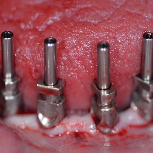
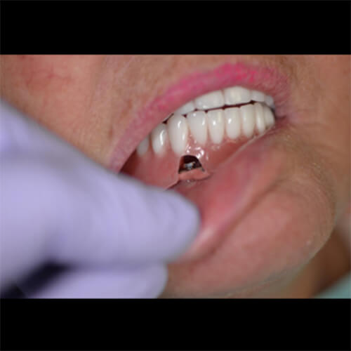
This patient is age 60+ and has been using a full denture for many years.
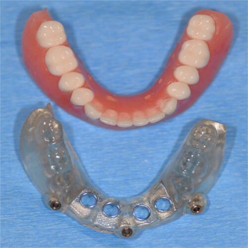
She was not satisfied with the lack of stability of her lower denture, but did not want the expense of a fixed bridge.
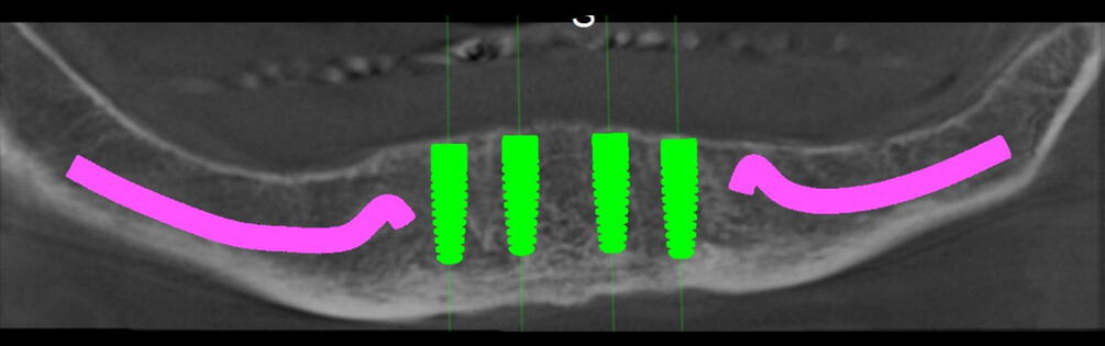
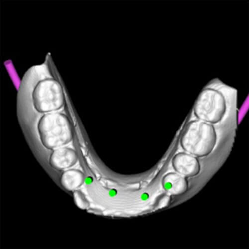
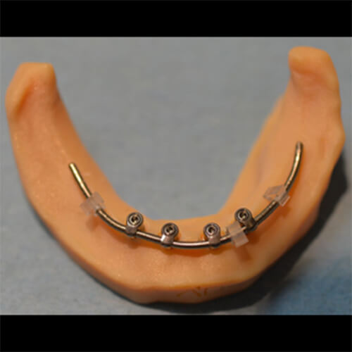
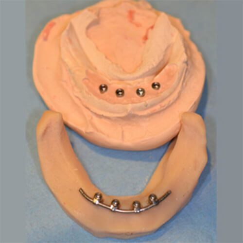
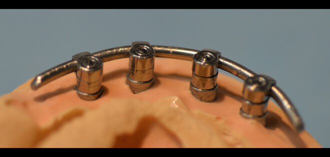
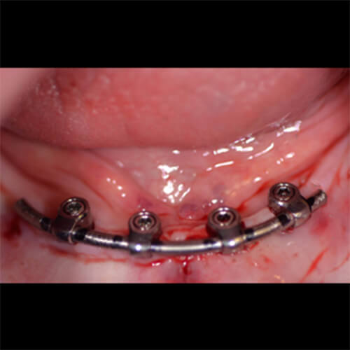
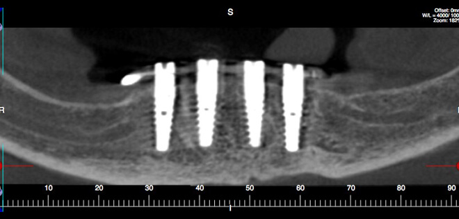
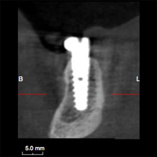
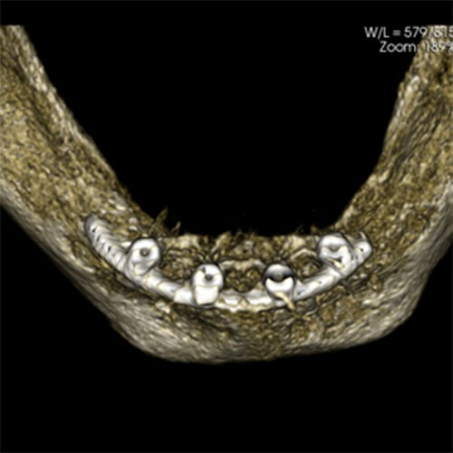
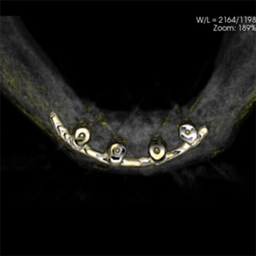
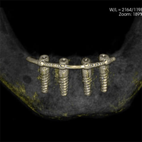
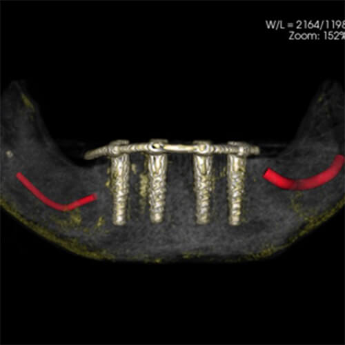
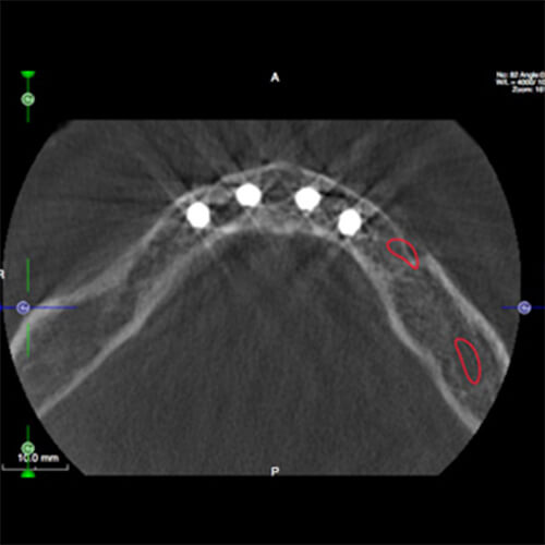
A.B. Dental’s P17 bar gives greater stability to the denture, with the advantages of the implants connected together.
The bar does not require a dental laboratory.