Dr. Peter Ovsishcher.
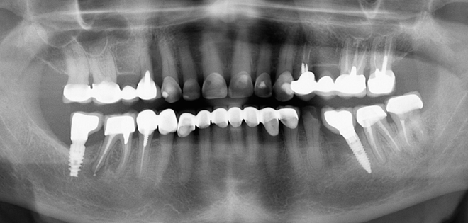
This female patient is 60+ and has no relevant medical history.
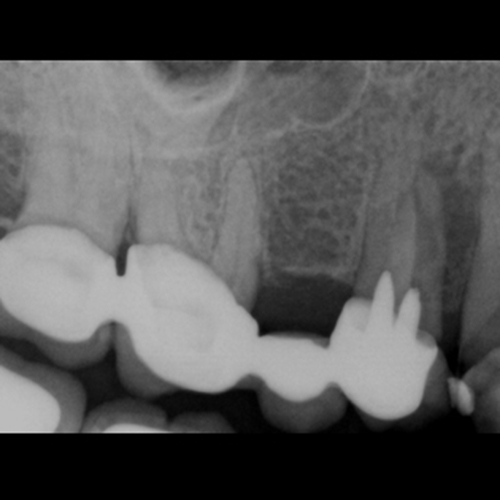
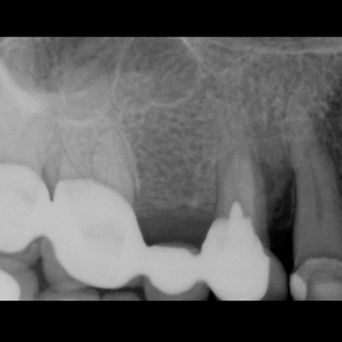
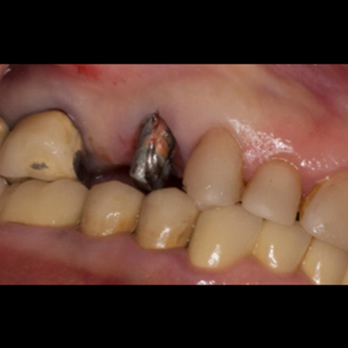
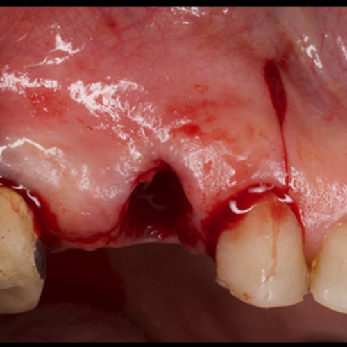
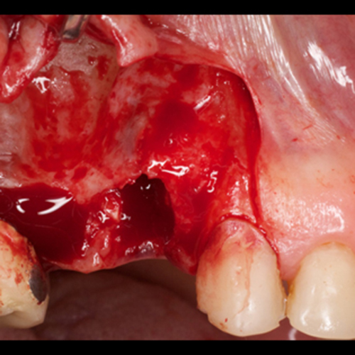
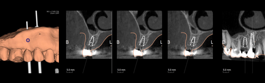
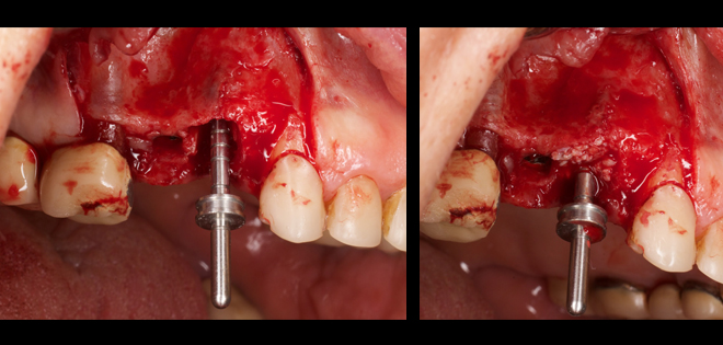
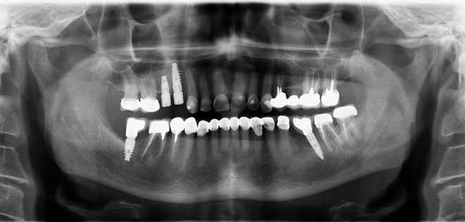
She has an infection at tooth 14 from a failed root canal therapy, resulting in severe bone loss around the root.
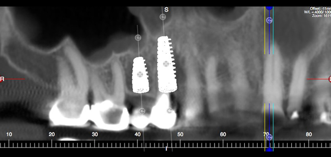
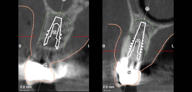
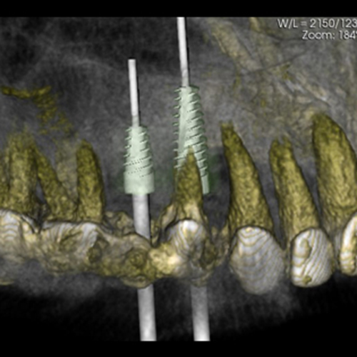
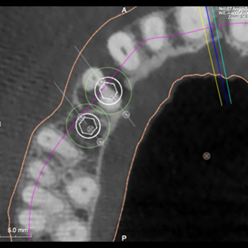
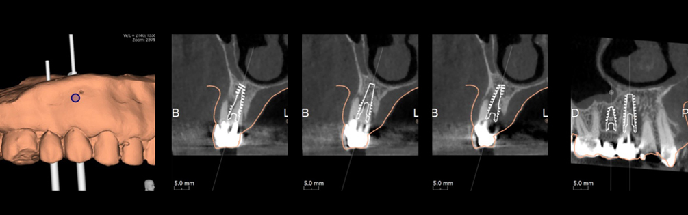
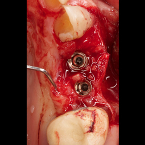
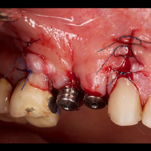
3D planning allows optimal visualization of the best options, and the implants are planned in the ideal positions, relating to prosthetics and the spacing between the implants and the adjacent teeth.
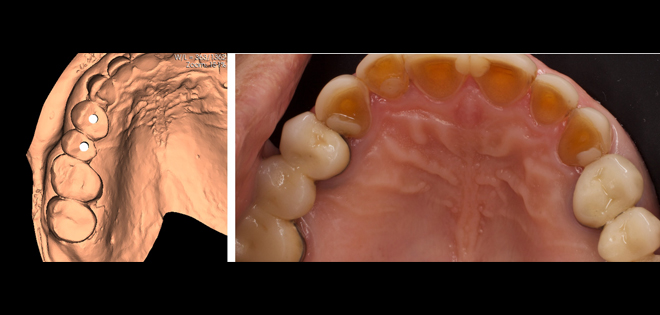
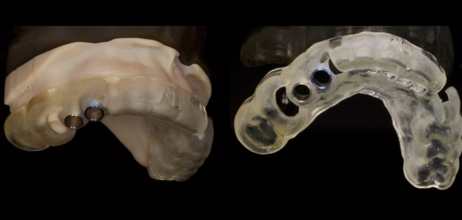
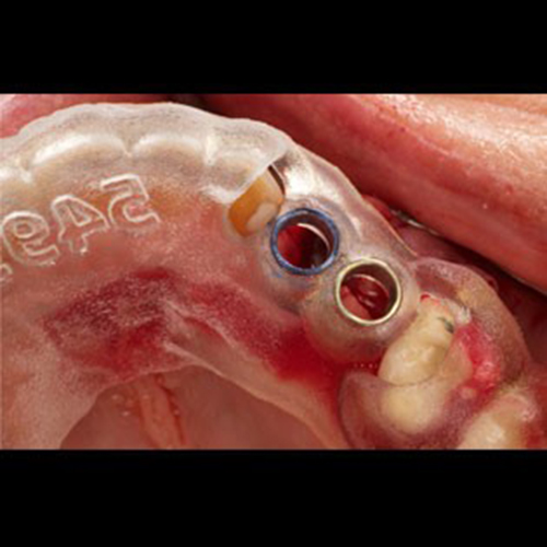
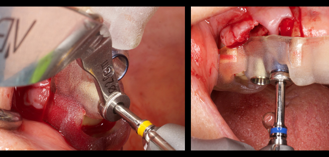
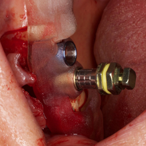
An AB Guide brings the virtual planning to the mouth. All drilling was made with the guide, and the implants were inserted through the guide. This is especially important with the extraction site at 14, where the guide keeps the planned implant position.