Dr. Gandhi Gunther.
A female patient with no medical issues.
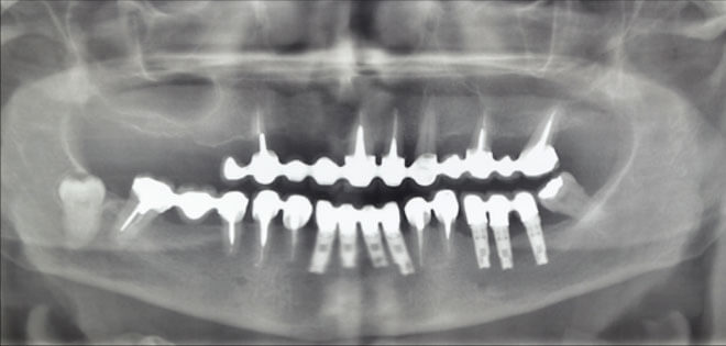
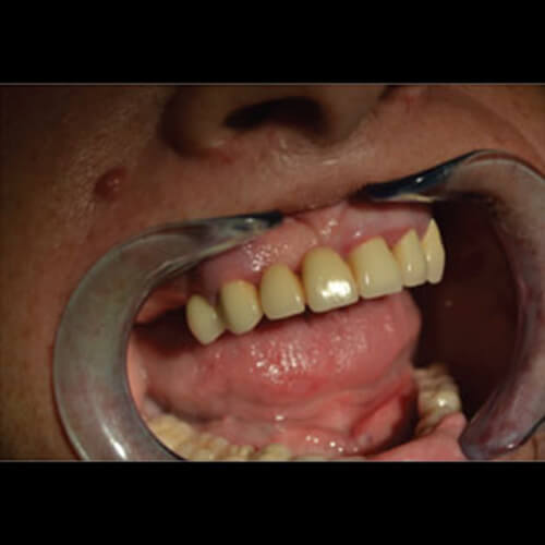
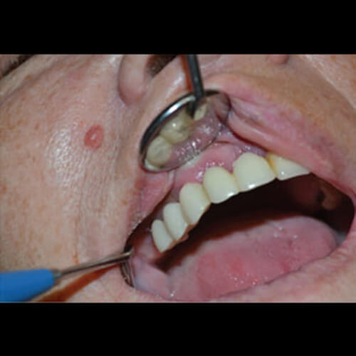
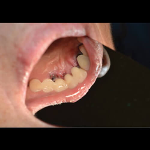
The upper jaw had a full bridge with a fracture in tooth 15.
This tooth supports a distal cantilever, because tooth 16 is missing.
The original treatment plan envisaged cutting the bridge and leaving only the left side, while placing a removable partial temporary denture on the right.
The patient rejected this solution.
Her preferred option – implants and a surgical split and immediate loading.
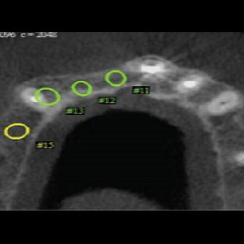
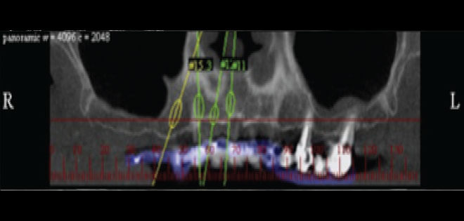
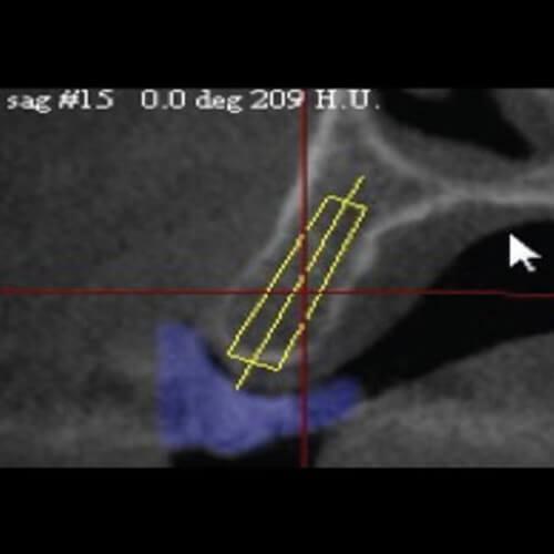
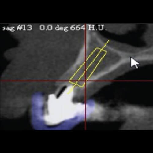
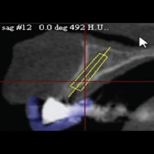
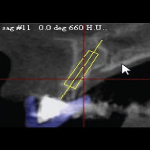
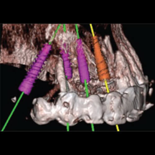
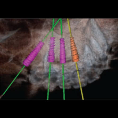
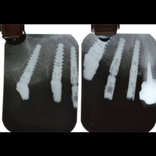
The plan included an inclined implant in the region of tooth 16, sparing the patient a sinus lift surgery.
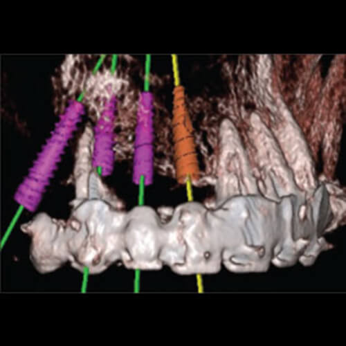
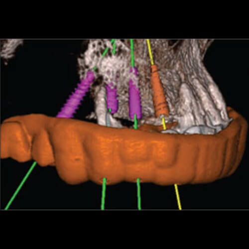
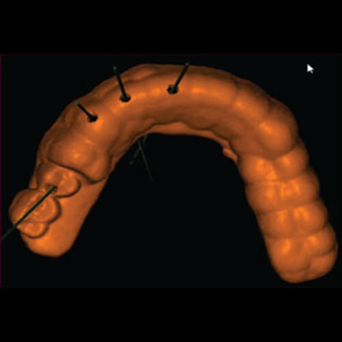
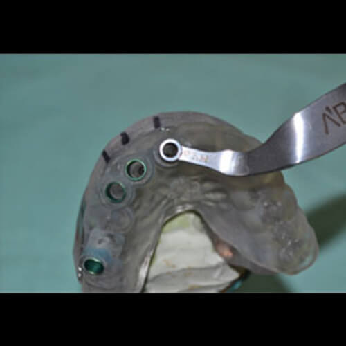
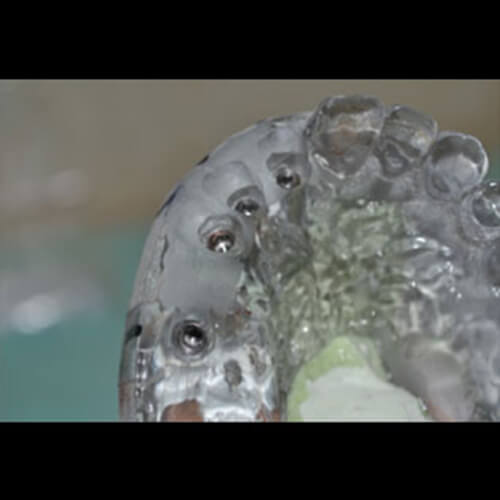
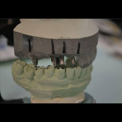
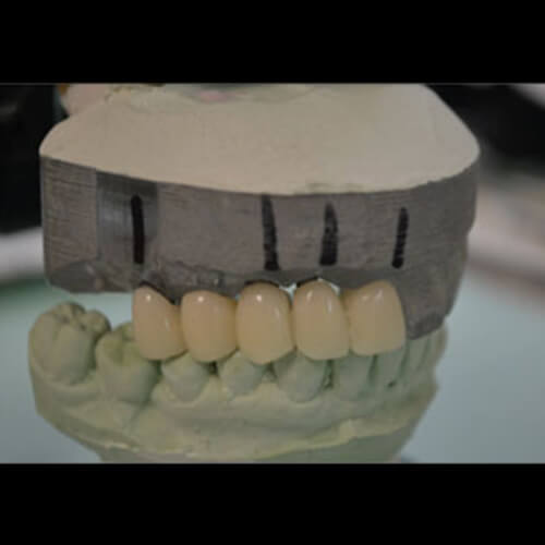
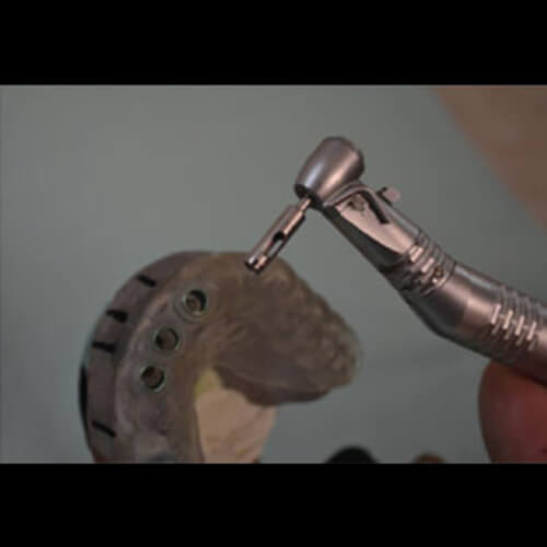
A temporary bridge (copy of the old bridge) was created according to a 3D model, integrating the position of the future implants.
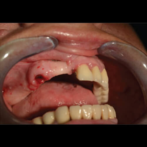
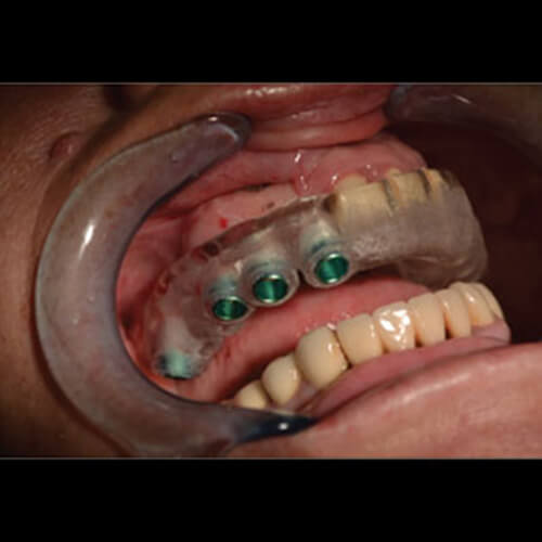
After an atraumatic extraction of tooth 15, implants were inserted (following the 3D plan and using a surgical splint) and immediate loading was performed.
The patient expressed satisfaction with the treatment outcomes, and the fact that the rehabilitation was both functional and aesthetic.